Stresses and strains
Prior to the analysis of the types of stresses and deformations that are subjected to a buried pipe, the main factors should be identified.
- Gravity forces: produced by pipe design elements, as follows:
- The pipe weight, which depends on the DN, the wall thickness and the pipe material.
- Permanent loads, due to the weight of construction elements or fixed installations that the pipe has to withstand.
- Load due to the weight of the fluid that conveys through the pipeline.
- Inner hydraulic pressure or working pressure.
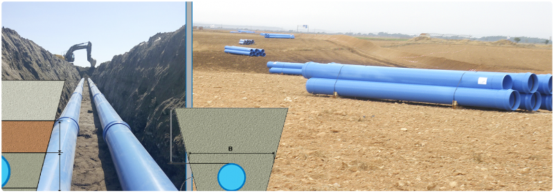
- Soil forces: generated by the soil conditions, which depend on the pipe installation, the type of anchoring and the type of associated filling owing the degree of compaction and the filling nature. Those assumptions lead to vertical loads and horizontal and side stresses.
- Overload forces: mainly dependant on the vehicles’ traffic above the pipe and the type of pavement.
- Groundwater forces: hydrostatic stress generated by underground water. Besides, under extreme conditions, climate factors (wind, snow, changes of temperature, etc.), and seismic and rheological factors, must be considered as well.
As a result, the main forces to consider in a PVC-O buried pipe are: the internal pressure, the field forces and the traffic.
- Gravity forces
Both the characteristics of the pipe and its working conditions play a relevant role in its resistance and deformation.
- Soil and backfill forces
The soil features involved in the soil load calculation are the following:
- Specific weight of the filling, (γ), in kN/m3. When trial data is not provided, γ = 20 kN/m3 is recommended.
- Internal friction angle of the backfill (ρ), in degrees.
- Friction angle between the backfill and the walls of the trench, (ρ'), in degrees.
- Coefficient of lateral pressure of the filling, K1 and K2.
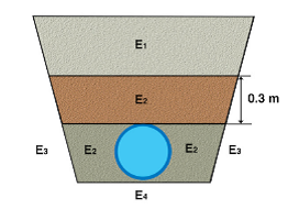
Compression modulus in different areas of the backfill and the trench, E1, E2, E3 y E4, in N/mm2.
- E1: Modulus resilience of the backfill from the top of the trench.
- E2: Modulus of resilience of the backfill around the pipe, up to 30 cm above the pipe crown.
- E3: Modulus of resilience of the soil at both sides of the trench.
- E4: Modulus of resilience of the soil below the trench.
Four types of soil can be considered::
- Group 1: Non-cohesive soils. This group includes loose gravels and sands. The particle size ф ≤ 0.06 mm should be lower than 5 %.
- Group 2: Slightly cohesive soils. This group includes slightly clayey or silty gravels. The particle size ф ≤ 0.06 mm should be between 5 % and 15 %.
- Group 3: Cohesive mixed soils. This group includes clayey or silty gravels and sands, cohesive stony residual soil. The particle size ф ≤ 0.06 mm should be between 15 % and 40 % and few plastic silts.
- Group 4: Cohesive soils. This group includes clays, silts and soils with a mixture of organic compounds.
As per the values of the backfill angle of inner friction (ρ), without trial data, UNE 53331 standard recommends the values as stated:
| Soil group | Angle of internal friction, ρ |
| 1 | 35⁰ |
| 2 | 30⁰ |
| 3 | 25⁰ |
| 4 | 20⁰ |
And from the backfill angle of inner friction, ρ, the backfill friction angle with the walls of the trench, ρ' is set, under the assumptions:
| Compaction | ρ’ |
| Backfill compacted in layers throughout the height of the trench | ρ |
| Backfill compacted layers in the tube without compacting the rest of the trench | 2/3 ρ |
| Backfill of the trench with subsequent compacting | 1/3 ρ |
| Shored trench, without a subsequent compacting to the table’s withdrawal | 0 |
Lateral thrust coefficients of the backfill are defined as follows:
K1: backfill coefficient used above the upper generatrix of the pipe.
K2: backfill coefficient used around the pipe up to the upper generatrix.
| Soil group | K1 | K2 |
| 1 | 0,5 | 0,4 |
| 2 | 0,3 | |
| 3 | 0,2 | |
| 4 | 0,1 |
The calculation of the compression modulus in different areas of the backfill and the trench, the CBR (California Bearing Ratio) method is applied, using a round plate with a 700 cm2 surface area. The Es values, in N/mm2, are given by the following expression:
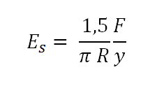
Where:
Es : Compression modulus, in N/mm2
R: Radius of the loaded plate, in mm.
![]() : Is the slope at the origin of the load curve (F) - base (y), obtained in the tests, in N / mm.
: Is the slope at the origin of the load curve (F) - base (y), obtained in the tests, in N / mm.
If trials are not performed, the values of E1 and E2 can be taken from the table below, according to the degree of compaction specified for the backfill and according to the type of soil.
It is possible to take E1 = E2 when the material and compaction of the backfill in both areas are the same. The values of E3 and E4 must be chosen according to the actual conditions of the land of the trench. If said values are known, it may be considered that E3= E2 and in installations under embankment, it will be assumed that E1 = E2 = E3.
For normal soils, E4 value is obtained from the table below.
| Compression modulus Es (N/mm2) | ||||||
| Soil Group | % Normal Proctor compaction | |||||
| 85 | 90 | 92 | 96 | 97 | 100 | |
| G1 | 2.5 | 6 | 9 | 16 | 23 | 40 |
| G2 | 1.2 | 3 | 4 | 8 | 11 | 20 |
| G3 | 0.8 | 2 | 3 | 5 | 8 | 14 |
| G4 | 0.6 | 1.5 | 2 | 4 | 6 | 10 |
- Overload forces
There are certain pressures on vertical pipes that can be divided as follows:
Concentrated overloads: These are caused by punctual traffic loads located on the wheels. To obtaining it, the value of the concentrated load, Pc, in kN, should be found:
| No | Symbol | Total load, (t) | Nr. of axis | a (m.) | b (m.) | Load per wheel (Pc) (kN) | |
| Front | Rear | ||||||
| 1 | LT 12 | 12 | 2 | 2 | 3 | 20 | 40 |
| 2 | HT 26 | 26 | 2 | 2 | 3 | 65 | 65 |
| 3 | HT 39 | 39 | 3 | 2 | 1,5 | 65 | 65 |
| 4 | HT 60 | 60 | 3 | 2 | 1,5 | 100 | 100 |
- Land height above the top of the pipe generatrix, H, in meters. When the pipe is installed under a paved area, the equivalent height, He, is used.
- Groundwater forces
The groundwater forces in an installation have a lower extend than the forces above detailed. The influence on the stress and deformation in a trench is minor when compared to the other installation parameters.
An important consideration related to the groundwater forces is the buoyancy of the pipe due to hydrostatic and uplift forces that require concrete ballast to be sized and installed to counteract this strain.
Results of the study cases
Influence of the trench and slope installation parameters.
There are several external factors that might be considered to validate the pipeline installation conditions. Characteristics related to Service pressure, traffic and type of soil are the factors with the greatest contribution.
| Parameter | Resistance ( stress ) | Strain | Importance |
| H1 | + | + | • • |
| B1 | + | + | • |
| Service pressure | + | - | • • • • • |
| Traffic / Pavement | + | + | • • • • |
| Groundwater level | + | + | • • |
| Alpha (2α) | + | - | • |
| Type of soil /Compaction | + | + | • • • • |
| Pipe design (DN, e and material) | + | + | • • • |
Molecor has implemented an online application for making all these mechanical calculations that will help to decide the best technical solution: www.tomcalculation.com
These calculations made are in accordance to the UNE 53331:1997 and ATV-DVWK-A 127E:2000 “Static Calculation of Drains and Sewers”, the most extended in Europe.